2. SEGA Chihiro
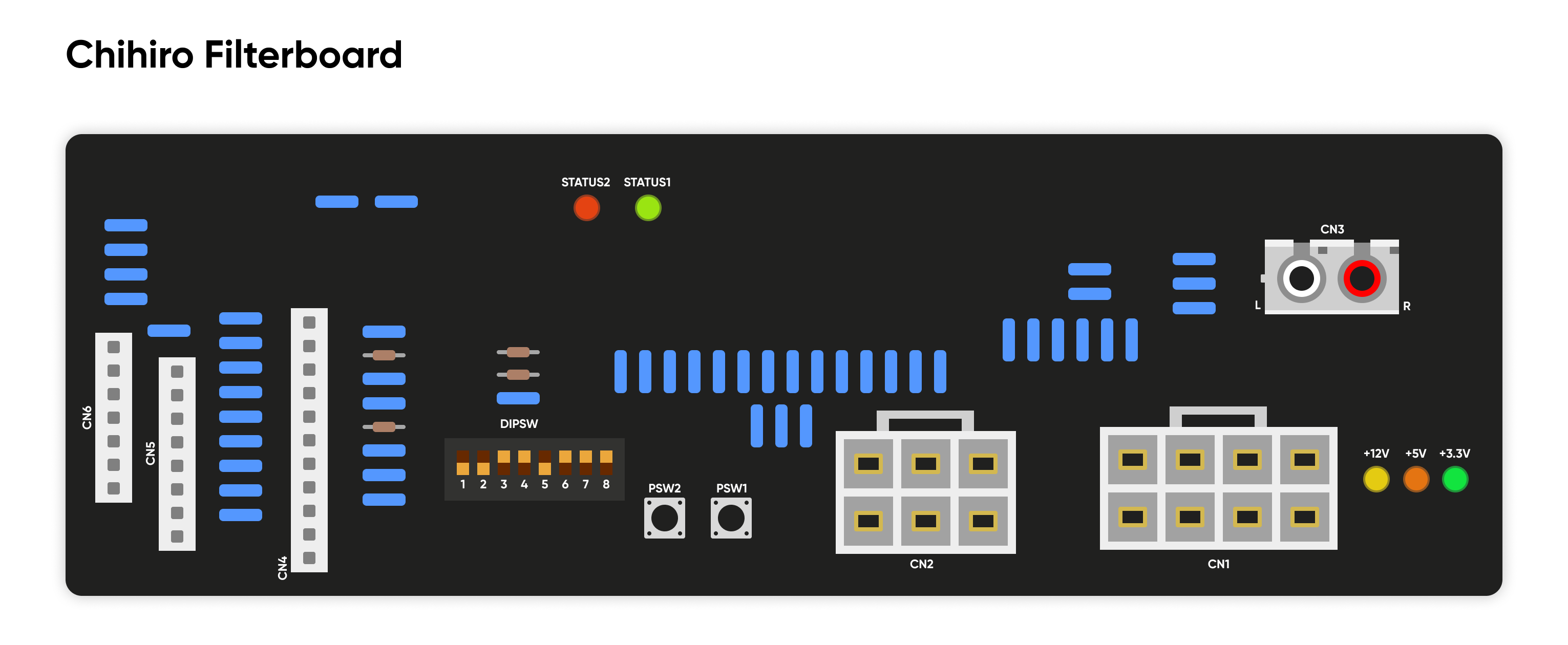
2.1 Board Overview
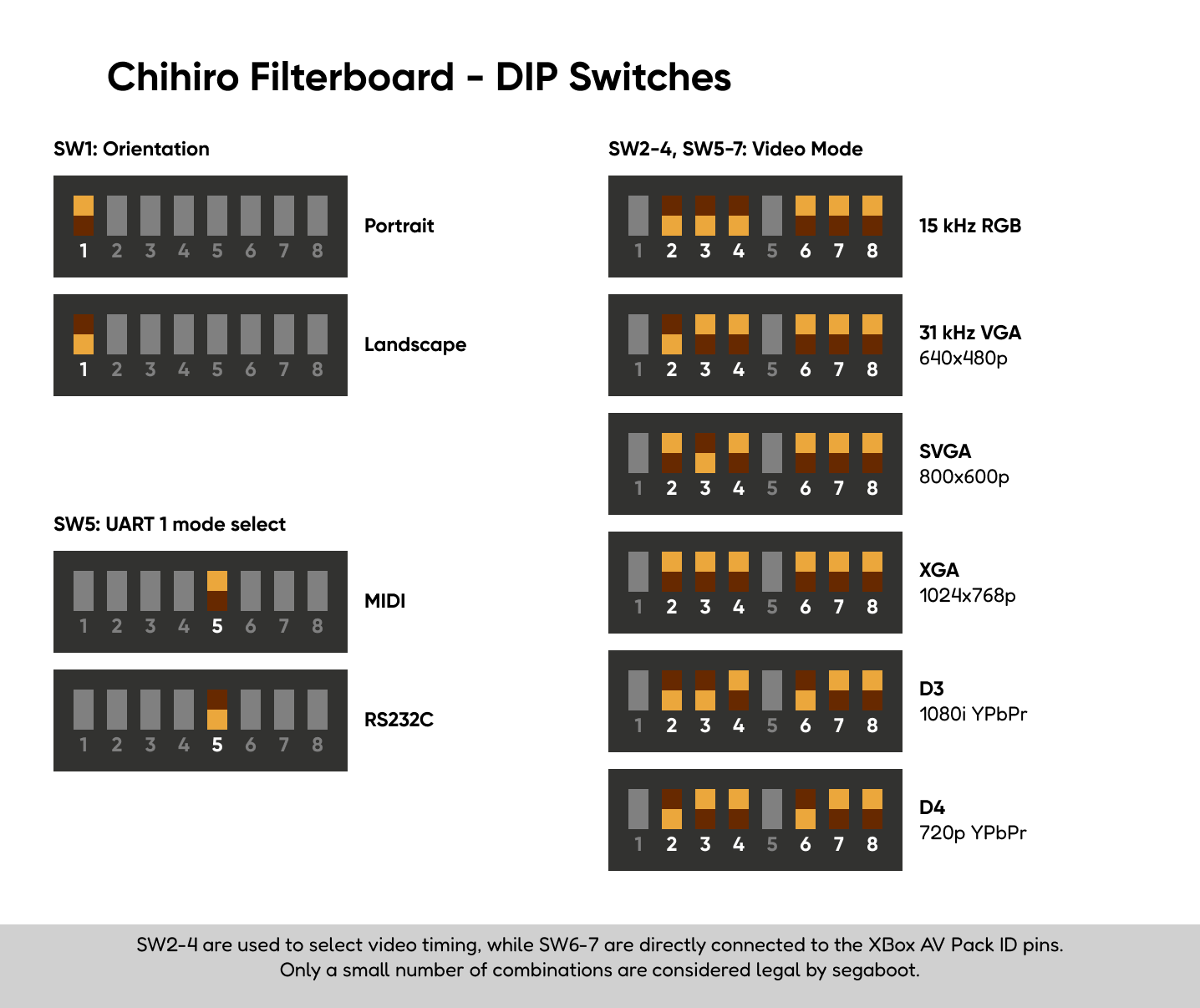
2.2 DIP Switch Settings
2.3 CN1 Power Diagram
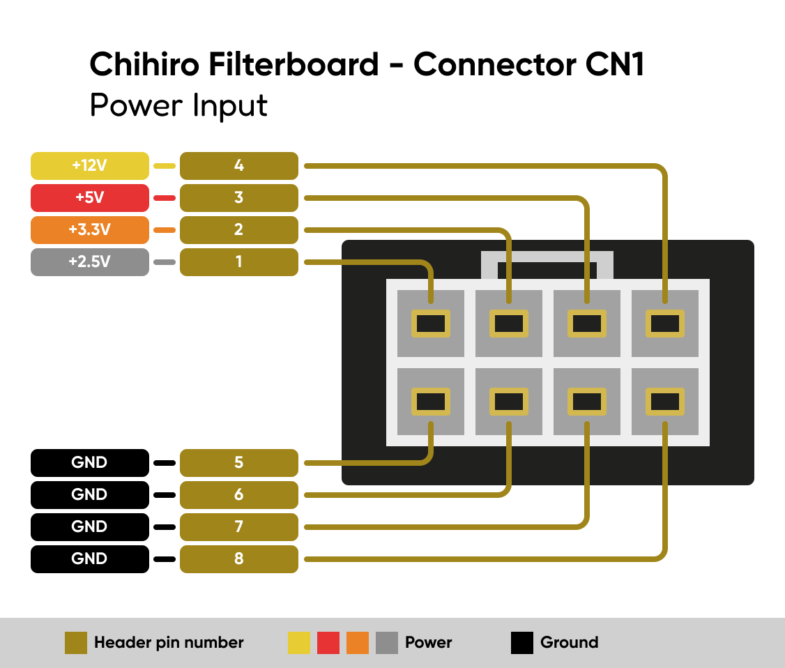
| Pin | Function |
|---|---|
| 1 | +2.5V |
| 2 | +3.3V |
| 3 | +5V |
| 4 | +12V |
| 5 | GND |
| 6 | GND |
| 7 | GND |
| 8 | GND |
2.4 CN2 Power Diagram
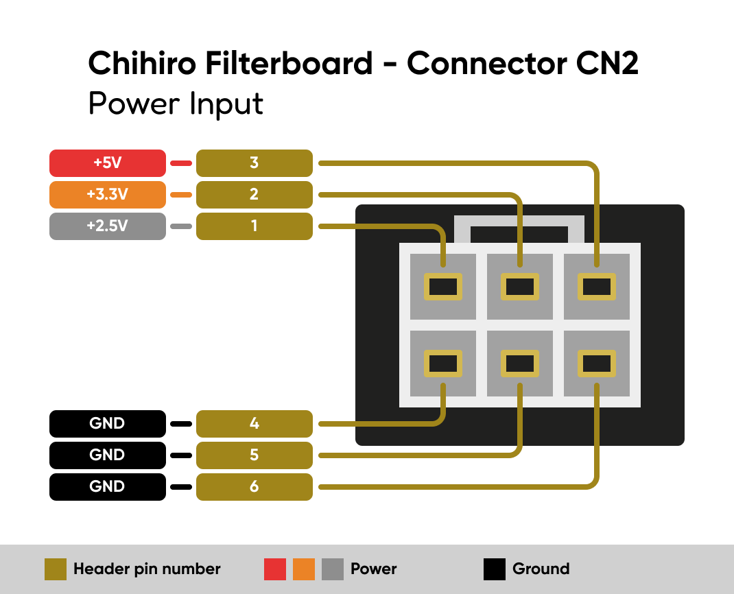
| Pin | Function |
|---|---|
| 1 | +2.5V |
| 2 | +3.3V |
| 3 | +5V |
| 4 | GND |
| 5 | GND |
| 6 | GND |
2.5 CN4 USB Diagram
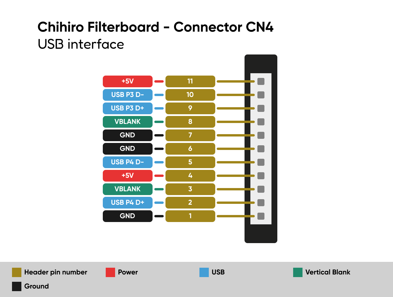
| Pin | Function |
|---|---|
| 1 | GND |
| 2 | USB P4 D+ |
| 3 | VBLANK |
| 4 | +5V |
| 5 | USB P4 D- |
| 6 | GND |
| 7 | GND |
| 8 | VBLANK |
| 9 | USB P3 D+ |
| 10 | USB P3 D- |
| 11 | +5V |
2.6 CN5 Serial UART Diagram
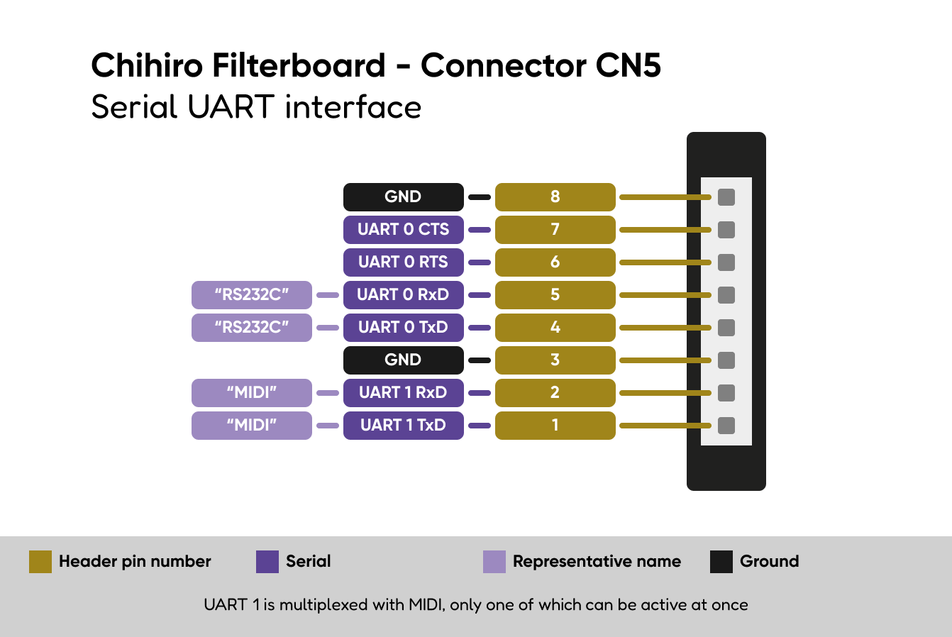
| Pin | Function |
|---|---|
| 1 | UART 1 TxD |
| 2 | UART 1 RxD |
| 3 | GND |
| 4 | UART 0 TxD |
| 5 | UART 0 RxD |
| 6 | UART 0 RTS |
| 7 | UART 0 CTS |
| 8 | GND |
UART 1 is internally referred to as the MIDI interface, even when in
UART function. UART 0 is internally referred to as the RS323C
interface.
2.7 CN6 MIDI Diagram
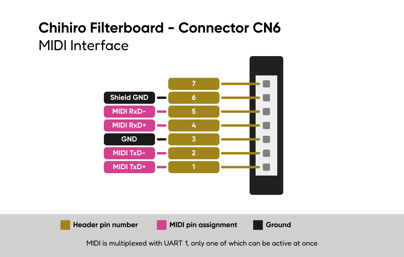
| Pin | Function |
|---|---|
| 1 | MIDI TxD+ |
| 2 | MIDI TxD- |
| 3 | GND |
| 4 | MIDI RxD+ |
| 5 | MIDI RxD- |
| 6 | Shield GND |
| 7 |